2018 TransiDupe-II relaunch

Exploded renders of 3D printed slide and negative carriers and mounting plate.
Camera scanning is a good method of digitizing slides and negatives. Adapters that mount directly onto the lens are easy to use but are problematic in that they tend to be tied to one particular lens, and attaching something large and bulky directly to your lens may damage the lens's internal parts. (And also have large tubes that take a long time to 3D print.)
So I switched to a method that mounts the slide/negative carrier away from the camera/macro lens. This works with any combination of camera body and macro lens.
New version for rail rig
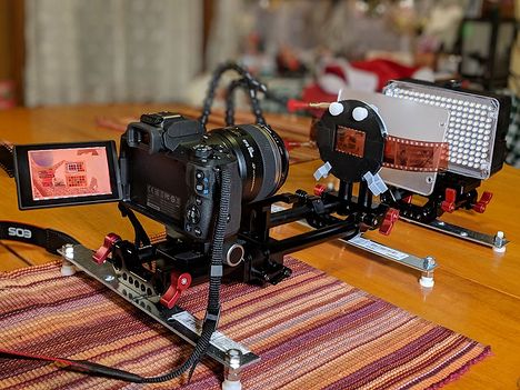
We use a rail rig to hold everything together.
This "rail rig" provides a stable base to mount the different components. There are sufficient adjustments so you can get everything lined up.
I used 5 inch mending plates from Home Depot to make the outrigger legs to keep everything from tipping over. I used nylon 1/4-20 3/4" thumbscrews to make the feet. I used 3/4" nylon thumbscrews and put nuts on the thumbscrews screws to increase the height. (The rail-rig adjusting knobs need clearance from the table.)
The rail-rig components mostly all came from Amazon and are surprisingly inexpensive. Read the comments I added in the parts list (below) to identify the different components that you see in these pictures.
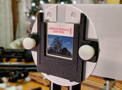
Slide carrier. Loosen the thumbscrews to adjust tilt
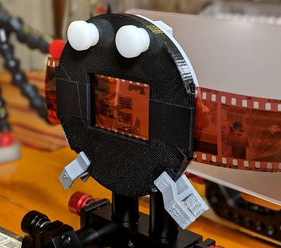
Negative carrier. Can also use 3/4 inch metal clamps.

Loosen the knob in the center to adjust the height
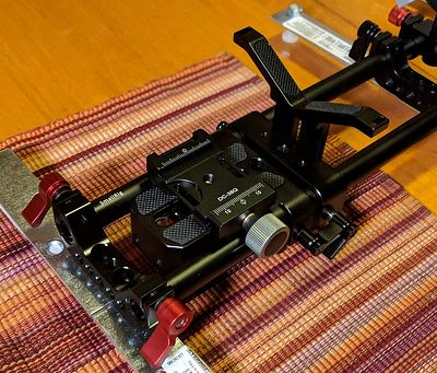
Camera mounts here on the Arca quick-mount
Loosen the knob in the center to adjust the height of the slide/negative carrier. When it is correct, tighten the knob.
Loosen the screws on the carrier mount to adjust side-to-side. The holes are enlongated.
Adjust the distance from the lens to the slide/negative carrier by sliding the camera back and forth on the rails while checking the focus on your live view screen. When you have the distance correct, lock down the rail knobs. You can make fine adjustments by moving the carrier mount back and forth but it is better to start out with this near the end of the rail and do the gross distance adjustment with the camera mount.
List of parts needed for new rail-rig version of TransiDupe
In addition to the 3D parts that are generated with the TransiDupe OpenSCAD file that need to be 3D printed, here is a list of the rail-rig parts that are available on Amazon. These are the parts that you see in the above photos. I added explanations in the list comments for each item. You need to click on the comment box to see the comments.
You don't need to buy everything in these lists! There are alternate versions of items that kept going in and out of stock while I was composing the lists. What you need are a pair of 12" 15mm rods, a quick-release adapter, something to mount the quick-release adapter to the 15mm rods, and something to mount the pair of vertical rails that the slide/negative carriers mount to. And probably the parts for the outriggers if you will be using it on a table and not mounting the rail rig on a tripod.
Vertical rods You'll need either one pair of 2 1/2" 15mm rods or one pair of 1 1/2" 15mm rods depending on how high your lens is above the rails. (Get one pair of each size.) The lens support is optional. Shrug, it doesn't hurt.
If you build a rail rig for the LED panel like I did you'll also need vertical rails for the LED.
Some of the items are listed several times because different versions keep going in and out of stock on Amazon.
Lights and lights part list
LED and diffuser Here is a second list for the lights.
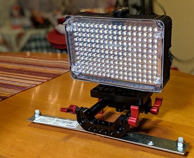
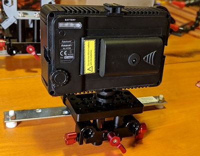
Rig to hold the LED panel
Loosen the center knob to adjust the LED panel's height
I tried various table-top tripods but none seemed suited to precisely adjust the height to the distance that is needed to backlight the slide/negative (alignment counts!), so I ended up making a second rig for the LED panel. It works well. (A Gorillapod also works.)
Look at the parts list for things with little clamps to hold the diffusion panel. Your choice.
Here is a link to a selection of Aputure H198 Amaran LED panels that I have.
It was chosen because it has a CRI and TLCI of > 95, a respectable R9, a spectrum that is really good for a LED panel, and has a CCT (color temperture) of about 5600K. For camera scanning we want the CCT to be in 5000K+ range. i.e. daylight. Bi-color LED panels only give half their light output at the daylight end.

Spectrum of Aputure H198 Amaran LED panal
Color science in a paragraph. CRI is a measure of how well a light renders color for human eyes. 0 == worthless, 100 == perfect. TLCI is roughly the same thing except for how cameras render color. CCT is the color temperature. Approx. 5,000K is daylight. Approx. 3,000K is tungsten. Duv (PDF) is a measure of color cast (tint). The lower the better. 0 == no color cast, >.007 == a color cast you can detect ("green tint", etc.) R9 is how well a light renders saturated red. (CRI does not measure saturated colors!) Red is the right end of the spectrum. It is also where lesser lights give up the ghost. Again, 0 (or less!) is bad. 100 == perfect. You can sort of detect this in the spectral plot in how far the flat part of the curve extends into red (the right).
See here for spectral tests of early LED panels and CFS. To show how horrible they were.
Improvements to OpenSCAD script
The biggest change is that TransiDupe (II) now supports the new OpenSCAD Customizer feature (that is patterned after the Thingiverse Customizer.) You need to install the latest development snapshot of OpenSCAD (Scroll down to "Development Snapshots" on the OpenSCAD download page
After starting OpenSCAD enable the customizer by following the instructions about "Activation of Customizer functions" here. (Edit/Preferences/Features and scroll down to the "customizer" option. Check it. Then View menu and uncheck Hide Customizer.)
Download and open TransiDupe-II.scad. If the Customizer is activated in OpenSCAD TransiDupe-II should look like this:
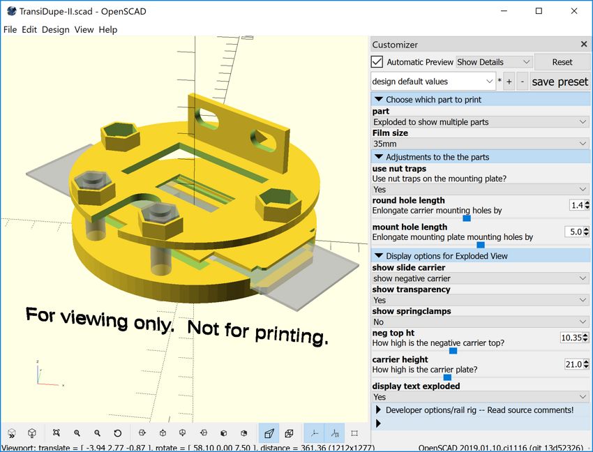
The Customizer is the panel on the right. I opened a few of the tabs for the screenshot--you will need to open them yourself. The customizer lets you quickly edit the important configuration variables without needing to directly edit the TransiDupe-II.scad code. For instance, select different parts under the "Which Part?" tab (it usually defaults to "Exploded", which shows you all the parts, but isn't printable itself. To print, you need to select each part, check if any of the other variables need changing, press "F6" to render (might take anywhere from a few seconds to the better part of a minute, depending on how complex the part is.) And then export (File/Export...) the part as an .stl file.
The customizer needs some explaining in that the variables that are shown in the Customizer don't dynamically update. For example, the variables for the "Display options for Exploded View" tab only are applicable to Exploded view. If you switch "part" to "Springpart slide carrier", all the options for "Display options for Exploded View" will still be on the screen but they won't affect anything. Because they only work when you are looking at Exploded View.
So if you aren't viewing "Exploded" you might better close the "Display options for Exploded View" tab because none of those variables will have any effect when you are looking at individual parts.
The options for the "Adjustments to the parts" tab, on the other hand, affect the parts and are applicable all parts. If the part is "Plate the slide and negative carriers mount to" and you toggle "Use nut traps" from "On" to "Off", this applies to the part itself. If "Use nut traps" is "Off" and you render (F6) and export to .stl, the part that is printed from the .stl file won't have nut traps.
If "Part" is "Clamp for negative carrier and plate" and you adjust the "springclamp height" slide, this will affect the part that will be printed after your render and export to .stl. "num springclamps" lets you increase how many spring clamps will be printed (from one to four.)
To visualize "springclamp height", switch to exploded view, then move the "neg top ht" and "carrier height" sliders all the way to the left. This collapses the expolded view so the components will be the way they are in actual use. Now you can adjust "springclamp height" and the springclamp's height will adjust accordingly. If you reduce the height it won't, however, deflect the way a real springclamp would, because this is beyond this model's capability (it will just sink down into the negative carrier.)
3MF support (.stl is dead now)
Or better yet export as an .3mf file. 3MF support is another new feature in the latest version of OpenSCAD (and probably also needs to be enabled (Edit/Preferences/Features and check "3mf-export")
The 3MF file format is designed to replace the old, gnarly .stl file format. If your slicer supports it, you are (probably) better off switching right now to exporting to .3mf instead of exporting to .stl. I had been trying to check my .stl files with MeshMixer. MeshMixer didn't like TransiDupe .stl files. They opened up with a lot of unfixable errors. But MeshMixer was happy as a clam with the same files in .3mf format.
TransiDupe: what is supported (and what isn't supported anymore)
Basically TransiDupe doesn't support the early versions of the project. This means the versions that had slits in the tubes and had rims on the disks. These versions were designed to be direct add-ons for the PhotoSolve Xtend-a-Slide. Because Photosolve is out of business and the Xtend-a-Slide isn't on the market anymore I ended up dropping support for these versions of TransiDupe. It was too difficult supporting all possible options without the OpenSCAD code fighting with itself.
What are supported is the version with complete tubes (what you see when part=exploded) and the version that works with 2" PVC pipe that you cut to length yourself. (See part options that have "pvc". e.g., select "Exploded view of PVC tube version" in the "Which Part?" dropdown.)